 |
 |
YouTube Video link: https://www.youtube.com/watch?v=YW_HXSbxZeM
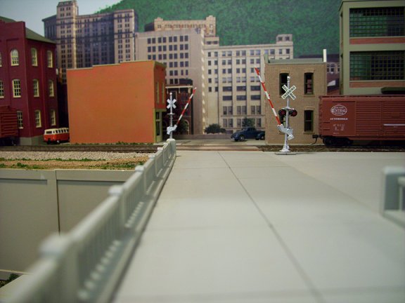
In actuality, building a grade crossing with gates is one of the more difficult and challenging tasks that you will run into. There are NO kits. There are NO instructions. There are only pieces and parts that you can buy, and then, even these are not complete. So where do you start?
You have to start with your imagination and "imagineer" how it needs to work and how to build it. Everyone will tell you you need to start with three main items:
1) a pair of crossing gates that will go up and down. Some will have lights on them as well. These you can buy.
2) a slow motion motor, usually a Tortoise Switch machine. This you can also buy.
3) an electronic control board. There are a couple of these available also.
But this is where it ends. No one will tell you how to build it or put all the parts together to make it work because there are different ways that it can be done and no two are the same. It is a complicated build, but if you think things through and take your time, it can be done. You will make mistakes along the way but just keep at it.
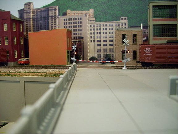
So lets take a look at what has to be done in general terms to make it work. First, the crossing gates must be by the tracks on the top of the layout. Everything else needs to be out of sight. The best place is under the layout. Next, they have to be right under the tracks that the grade crossing protects. That means some type of mounting shelf. It would be helpful if it were removable so that you could put all the parts on it and then mount it underneath. Next you will need some type of linkage to go from the motor to each grade crossing gate. That covers the mechanical portion. Then there is the electrical part. Sensors with a circuit that would trigger the motor to lower the gates, ring the crossing bell, and flash the crossing lights.
Now lets put these things in a list:
1) A pair of crossing gates that will go up and down.
2) A slow motion motor, usually a Tortoise Switch machine.
3) An electronic control board.
4) Start and stop sensors.
5) A linkage system from the motor to the crossing gates.
6) A sound module to make the bell sound.
7) A speaker for the sound.
8) A board or shelf to mount all the components on.
The following drawings and photos show how I built my animated grade crossing with gates and may help you build yours.
|
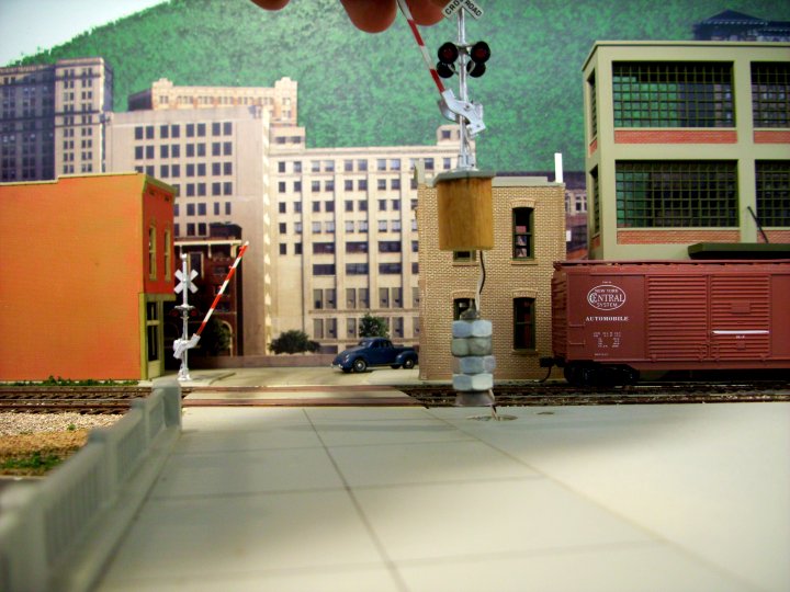
I modified my NJ International crossing gates by removing the stiff wire that was used to make them go up and down. I decided to use a mono filament fishing line because it was flexible and hard to see. I also added a mounting plug to keep the gates in the same place and to feed the fishing line and electrical wires through. A weight was added to keep the gates up. The theory that I used was I would push the weight up allowing the gates to go down. |
| This diagram shows how one gate is
hooked up. The crossing gate can be removed independently of the
mechanism by letting the weight slip into a hollow tube. There is
a sliding plug in the tube to act as a floor that raises and lowers the
weight. A Tortoise is used for the motor, and when it moves, the
belcrank changes the direction of movement to up and down. The
inverted V bend in the linkage (a brass wire) allows for minor
adjustments in the length of the wire. As you can see, everything is mounted on a base mounting plate. Mine is a piece of plywood. One thing to make note of: Once you draw a diagram of how you want your system to be built, things will always change in one way or another. You will see differences between these drawings and the photos of my actual mechanism, but the principal remains the same. The electronic circuit boards can also be mounted to the base mounting plate. |
|
|
This drawing shows what is needed for two crossing gates. (The gates are not shown here.) It also shows a couple of mounting blocks (wood) to hold the base mounting plate to the layout at a specified distance from it. Note also that the belcrank on the right is different from the one on the left. As the Tortoise link moves one way, both sliding plugs move in the same direction. |
 |
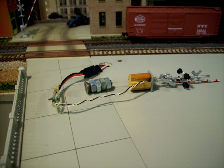 |
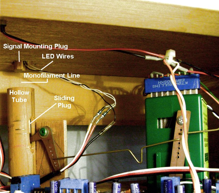
The crossing gates can be removed. The wires for the LEDs are on a connector also. The weights are made from nuts and bolts.
 |
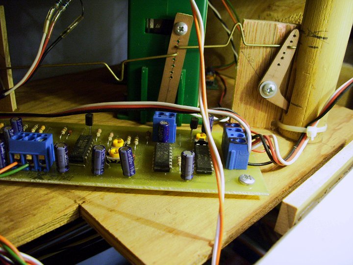 |
On the left photo you see both tubes, the Tortoise, linkage, and belcranks, along with the main circuit board used for control.
The tubes I used were made of wood, but you can use almost anything. PVC or CPVC would make good tubes also.
The sliding plugs are sections of dowel that just fit inside the tubes and slide freely without tipping.
 |
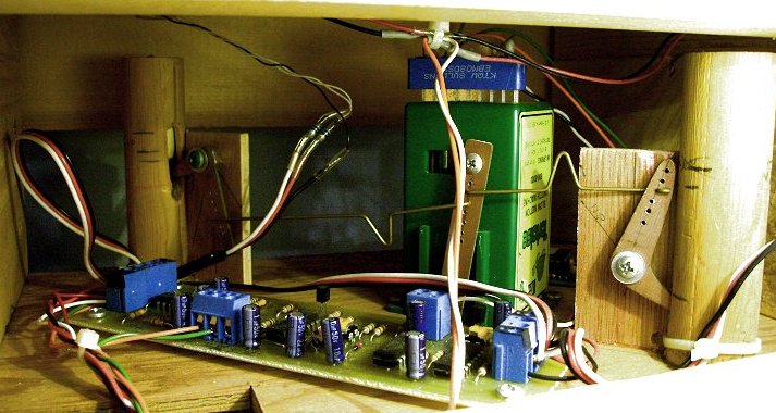
The belcranks here are hand made of printed circuit board material. The motion arm on the Tortoise pivots at the bottom in the mounting board.
The electronic board I use is from Rob Paisley. It flashes the LEDs and turns the bell circuit (a separate board) on and off, plus activates the Tortoise.
http://home.cogeco.ca/~rpaisley4/AGC11.html